- 您现在的位置:买卖IC网 > Sheet目录39245 > LM12H458MWG-MCP (NATIONAL SEMICONDUCTOR CORP) SPECIALTY ANALOG CIRCUIT, CDFP44
6.0 Application Circuits (Continued)
DS011264-26
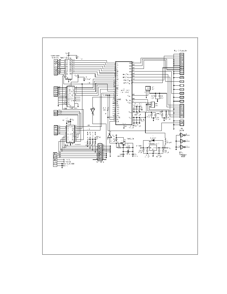
Note: The layout utilizes a split ground plane. The analog ground plane is placed under all analog signals and U5 pins 1, 34–44. The remaining signals and
pins are placed over the digital ground. The single point ground connection is at U6, pin 2, and this is connected to the motherboard pin B1.
FIGURE 16. Schematic for the LM12(H)454/8 Evaluation Interface
Board for XT and AT Style Computers, Order Number LM12458EVAL
www.national.com
34
发布紧急采购,3分钟左右您将得到回复。
相关PDF资料
LM12H458MWG/883
SPECIALTY ANALOG CIRCUIT, CDFP44
LM1262NA/NOPB
3 CHANNEL, VIDEO PREAMPLIFIER, PDIP24
LM129BH/883
1-OUTPUT TWO TERM VOLTAGE REFERENCE, 6.9 V, MBCY2
LM129BH
1-OUTPUT TWO TERM VOLTAGE REFERENCE, 6.9 V, MBCY2
LM12H454CIV
SPECIALTY ANALOG CIRCUIT, PQCC44
5962-9319501MXC
SPECIALTY ANALOG CIRCUIT
5962-9319502MYX
SPECIALTY ANALOG CIRCUIT, PQCC44
5962-9319501MYX
SPECIALTY ANALOG CIRCUIT, PQCC44
相关代理商/技术参数
LM12L438CIV
制造商:NSC 制造商全称:National Semiconductor 功能描述:Sign Data Acquisition System with Serial I/O and Self-Calibration
LM12L438CIWM
制造商:NSC 制造商全称:National Semiconductor 功能描述:Sign Data Acquisition System with Serial I/O and Self-Calibration
LM12L454CIV
制造商:Rochester Electronics LLC 功能描述:- Bulk 制造商:Texas Instruments 功能描述:
LM12L458
制造商:NSC 制造商全称:National Semiconductor 功能描述:12-Bit + Sign Data Acquisition System with Self-Calibration
LM12L458_06
制造商:NSC 制造商全称:National Semiconductor 功能描述:12-Bit + Sign Data Acquisition System with Self-Calibration
LM12L458CIV
功能描述:模数转换器 - ADC RoHS:否 制造商:Texas Instruments 通道数量:2 结构:Sigma-Delta 转换速率:125 SPs to 8 KSPs 分辨率:24 bit 输入类型:Differential 信噪比:107 dB 接口类型:SPI 工作电源电压:1.7 V to 3.6 V, 2.7 V to 5.25 V 最大工作温度:+ 85 C 安装风格:SMD/SMT 封装 / 箱体:VQFN-32
LM12L458CIV/NOPB
功能描述:模数转换器 - ADC RoHS:否 制造商:Texas Instruments 通道数量:2 结构:Sigma-Delta 转换速率:125 SPs to 8 KSPs 分辨率:24 bit 输入类型:Differential 信噪比:107 dB 接口类型:SPI 工作电源电压:1.7 V to 3.6 V, 2.7 V to 5.25 V 最大工作温度:+ 85 C 安装风格:SMD/SMT 封装 / 箱体:VQFN-32
LM12L458CIVF
制造商:Rochester Electronics LLC 功能描述:12-BIT PARALLEL I/O DAS - Bulk